Navigation switchboard: separate feeders and connected loads
RS and RKO rules: practical application
Two devices with the same supply voltage do not form a complete shipboard navigation power system. Before ordering NED-3010 or NGR3000 identify the supply for each set and the circuits that will remain on the existing switchboard. The RS Rules address this separately from sizing a power supply for the total load.
Scope
This guide uses section 2.2 of Part V, Navigational Equipment, of the Rules for the Equipment of Sea-Going Ships, edition dated 1 January 2026. Clause 1.1.1 applies this Part to self-propelled ships not engaged in international voyages and to their navigational equipment. Determine the applicable edition and requirements for the vessel from its documents. Under clause 1.1.3, additional instructions of the flag State maritime administration take precedence in case of conflict.
Section 2.2 also covers emergency power and refers to other Parts of the Rules. Reviewing the common switchboard therefore does not establish the adequacy of the entire power system. Power to a position source used by the GMDSS radio installation is discussed separately in the relevant article in this series.
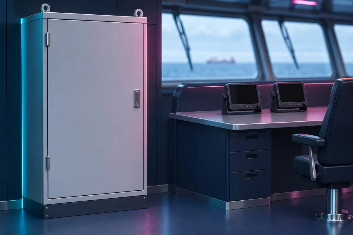
Common switchboard and separate feeders
Under clause 2.2.2, electrically powered navigational equipment must be supplied through separate feeders from a common navigational equipment switchboard. The clause expressly excepts the ship's heading or track control system. Its supply is addressed separately under clause 2.2.5, which refers to Part XI of the Rules for the Classification and Construction of Sea-Going Ships.
A common switchboard still has separate outgoing circuits. The design schedule should show which feeder serves each type of equipment. When replacing one device, this helps identify the affected part of the system without assuming the existing wiring has already been accepted.
Clause 2.2.6 requires circuit breakers on outgoing switchboard circuits to each type of navigational equipment. Select ratings, protective devices, and cable parameters using the design, loads, and applicable requirements. The clause does not specify one breaker rating for all navigation receivers or echo sounders.
Loads unrelated to navigation
Clause 2.2.7 prohibits connecting loads unrelated to navigational equipment to its switchboard. Check this when surveying the existing station. A free position on the switchboard alone does not establish that a new load may be connected.
State the purpose of each connection to be retained. If a device cannot be identified or the diagram does not match the installation, flag it for survey and a design decision. This article does not advise disconnecting unknown circuits.
| What to include in the design inputs | What this establishes |
|---|---|
| Switchboard and current power diagram | Establish the existing power distribution arrangement. |
| Equipment list and purpose of each circuit | Distinguish navigation loads from other loads. |
| Existing outgoing circuits to retain and proposed circuits | Define the scope of replacement and design work. |
| Protection, cables, and load data | Provide the inputs needed to specify the solution. |
| Unidentified connections | Identify what needs to be surveyed before installation. |
Coordinate the power diagram with the supply package
The NED-3010 is a marine echo sounder and the NGR3000 is a GNSS navigation receiver. These are actual catalog examples. Both serve navigation, but that does not establish identical electrical loads or interchangeable power circuits.
For a quotation, provide the exact equipment variants, vessel documents, equipment to be retained, and existing diagrams. Define the survey, required modifications, installation materials, and post-installation checks in the work scope. The supplier and contractor should agree on what belongs to the new package and what remains part of the existing ship system.
Power supply sizing and distribution design address related questions. Spare capacity alone does not establish compliance with feeder, protection, and load requirements. Make the final decision using the design and the manuals for the specific equipment.
Source: RS, Part V, Navigational Equipment, edition dated 1 January 2026, clauses 1.1.1 and 1.1.3 and all of section 2.2. The roles of the models are documented on the official NSR NED-3010 page and NGR-1000/NGR-3000 page. Verify exact specifications against the documentation for the offered variant.
More in this series
- Portable GMDSS: gloved operation and readiness for use
- New equipment near the magnetic compass: what to agree
- Echo-sounder trunk: access and water detection
- AIS: accounting for audible fault alarms
- NGR3000 antenna: information needed before choosing a location
- Echo-sounder cable: routing, shielding and deck connections
- EPIRB: float-free release and access to the container
- AIS-SART: the mounting arrangement is part of the package
- NTW-1000: checking the emergency-battery expiry date
- Echo-sounder transducer: conditions around the installation site
- Position source for GMDSS: include power supply in the brief
- AIS pilot plug: what to agree for the bridge
- DSC watchkeeping: the alarm must cover the whole bridge
- NAVTEX: bringing an SAR message to the watchkeeper's attention
- Speed log for a project: speed through the water or over the ground
- EPIRB for a particular vessel: data, markings and documents
- AIS class in the enquiry: start with the vessel's requirement
- Portable GMDSS: storage and transfer to survival craft
- Marine VHF antenna system: what to include in the work specification
- Charging the radio reserve battery: monitoring on the bridge
- Replacing an echo sounder: installation design and onboard documents
- EPIRB Checks: Self-Test and Supporting Document
- Grounding a navigation instrument: what to include in the design