Marine VHF antenna system: what to include in the work specification
RS and RKO rules: practical application
When upgrading marine VHF equipment, a quotation for a radio alone leaves an important question open: which antenna system will support its operation on the particular vessel. For the NSR NVR-3000 in our catalogue define the supply boundaries from the outset: the new radio, antennas and feeders to retain, and the intended work. Quotation comparisons will then cover the complete agreed installation rather than just a unit on a desk.
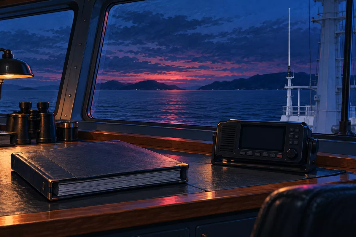
The vessel to which the requirements relate
This article discusses Part VII of the RKO Rules for the Classification and Construction of Ships, as amended by Order No. 29-p dated 31.03.2026, sections 5.1, 5.2 and 5.7. It concerns shipboard radio equipment on vessels of RKO class. Specify the class, purpose, navigation area and work status in the enquiry. For an existing vessel, the applicable edition is established taking clause 1.1.2 into account; additional Administration instructions are considered under clause 1.1.5. Discussing these clauses does not constitute approval of a particular antenna or new installation.
The NVR-3000 is considered here for its documented role: the manufacturer describes a marine VHF GMDSS radio with Class A DSC and channel 70 watch. Brochure rev15.1 lists NVA100 antennas as options. Purchasing the radio itself therefore does not confirm that a complete antenna system is included; the exact package must be specified separately.
Start with a schedule of the existing installation
For a replacement, provide identifiers of all retained components, available equipment documents and an antenna layout. Note the feeder length and markings, outdoor connections, any devices in the antenna path and known damage. Identify an unknown configuration as a survey question. An externally intact cable jacket does not establish the cable's electrical parameters.
| Part of the specification | Information to provide | What the quotation should provide |
|---|---|---|
| Radio station | Model, workstation purpose and operating modes | Exact NVR-3000 version and radio package |
| Antenna and mounting | Identifier, documents and operating conditions | Confirmed model and its supply boundaries |
| Feeder and connections | Type, length, route and outdoor connectors | New and retained components with loss data |
| Location and outcome | Mast plan, nearby equipment and verification procedure | Agreed scope of design, work and records |
This schedule is particularly useful when one contractor offers to replace only the radio while another includes a new cable run. The difference in scope becomes clear before the total prices are compared. It also helps establish who confirms the condition of retained cable and who is responsible for the specified measurements after the work.
Height and the antenna surroundings
Clause 5.2.1 requires the greatest height practicable within the vessel's design, but no higher than the lightning air terminal, unobstructed field propagation and sufficient separation from potential emission sources for electromagnetic compatibility. LED navigation lights are named as an example in the rule. Where practicable, VHF and UHF antennas are placed at different vertical levels; clause 5.2.2 specifies vertical polarization.
The enquiry therefore needs a plan of the existing mast with nearby antennas and equipment. A close-up photograph of a whip alone does not show these surroundings. Clause 5.2.3 gives mandatory GMDSS VHF antennas priority over other VHF antennas. If they are at the same level, their separation must be at least five metres. This is a condition of the clause, rather than a universal distance between any devices on a mast.
Mechanical and environmental suitability must be confirmed separately. Under clause 5.1.2, antennas on inland-navigation vessels must withstand wind pressure corresponding to speeds up to 29 m/s, and those on mixed-navigation vessels up to 60 m/s, from any direction; vessel speed and other factors are not included. The label marine and a similar frequency range do not, by themselves, resolve this issue. The quotation needs data for the particular version offered.
Feeder losses and measurement results are different information
Clause 5.2.4 specifies double-screened cable with a maximum attenuation of 3 dB. Outdoor coaxial connectors must be waterproof by design, protecting the cable against water ingress. The specification therefore needs the cable type, actual length and connector identifiers; a general antenna cable entry is insufficient to compare options.
Under clause 5.7.14, reflected power in the VHF and UHF antenna path must not exceed 10% of the measured output power. Antenna documentation and cable-loss data do not constitute the result of this measurement on the installed system. Agree on the intended check, its conditions and the form of its record with responsible specialists using the applicable documents. This article provides information for ordering, rather than instructions for taking measurements yourself on a transmitting installation.
Obtaining a comparable quotation
Send an NVR-3000 enquiry with four attachments: vessel details and applicable requirements, a schedule of retained equipment, an antenna layout and the expected scope of work and documents. Separate new products, survey work, design decisions and post-installation verification. Ask the supplier to identify confirmed items and the information still needed. Price, availability, version and delivery time are clarified for this scope; a radio model name alone does not imply any promised range in kilometres.
Sources: RKO: amendment to Part VII under Order No. 29-p, 1.1.2, 1.1.5, 5.1.2, 5.2.1–5.2.4, 5.7.14; NSR NVR-3000, brochure rev15.1.
More in this series
- Portable GMDSS: gloved operation and readiness for use
- New equipment near the magnetic compass: what to agree
- Echo-sounder trunk: access and water detection
- AIS: accounting for audible fault alarms
- NGR3000 antenna: information needed before choosing a location
- Echo-sounder cable: routing, shielding and deck connections
- EPIRB: float-free release and access to the container
- AIS-SART: the mounting arrangement is part of the package
- NTW-1000: checking the emergency-battery expiry date
- Echo-sounder transducer: conditions around the installation site
- Position source for GMDSS: include power supply in the brief
- AIS pilot plug: what to agree for the bridge
- DSC watchkeeping: the alarm must cover the whole bridge
- NAVTEX: bringing an SAR message to the watchkeeper's attention
- Speed log for a project: speed through the water or over the ground
- EPIRB for a particular vessel: data, markings and documents
- AIS class in the enquiry: start with the vessel's requirement
- Portable GMDSS: storage and transfer to survival craft
- Charging the radio reserve battery: monitoring on the bridge