What does the CER show?
The CER shows how much power is returned back to the transmitter instead of going to the air.
A unit would mean perfect alignment, but that doesn’t happen in life.
The value of up to one and a half is considered the norm, up to two is tolerable, above two is an excuse to look for a cause.
High CSV not only eats power: it warms the output cascade and shortens its life.
With very poor coordination, the transmitter protection loses power, and the communication disappears without any visible breakdown.
Where the signal is actually lost
The antenna is only part of the tract, and it is not always to blame.
Connectors cause more problems than cable: water, oxide and poor soldering live there.
The cable loses more the higher the frequency and the longer it is, and this is a loss, not a reflection.
The extra length, curled up in the bay at the base of the mast, works against you at all frequencies.
The adapters multiply the number of contacts, and each adds its own contribution to the losses.
What to measure on board
The simplest CSV meter is switched on between the station and the feeder and shows the picture at one point.
The device with scanning frequency is more useful: it immediately shows which parts of the range the coordination is worse.
The analyzer with the measurement of the distance to heterogeneity directly indicates which meter of cable fault.
Measurement should be on working power and on several channels, not on one convenient one.
Measurement is recorded: without past figures, it is impossible to understand whether it has become worse or it has always been so.
How to distinguish an antenna from a connector
If the CSV is bad at all frequencies, suspicion falls on the connector or cable.
If it grows only to the edges of the range, it is more often the antenna itself and its tuning.
Replacing a short jumper cable at the station is the quickest check to make.
Connecting a load equivalent instead of an antenna separates the path from the device in one minute.
If the equivalent is all right, and the antenna is not, then go on the path from the station to the mast.
Features of the HF-Tract
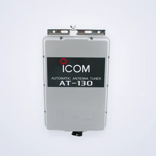
On short wavelengths, the antenna is almost never aligned on its own, and the tuner is responsible.
The tuner is placed at the base of the antenna, and not next to the station, otherwise it coordinates the cable, not the emitter.
The grounding and counterweights in the HF track mean more than the antenna itself: on a ship, it's the hull.
Insulators should be clean: salt plaque on them takes some of the power to nowhere.
After any work on the mast, the tuner is forced to go through the approval cycle again.
Procedure for seasonal inspection
Check connectors and sealing, starting from the top.
We measure the CSV on several channels and compare it with last year’s record.
Check the tightening of the fasteners and the integrity of the plough at inflection points.
See if there are new antennas nearby that interfere with each other.
The result is recorded in the same journal where the past measurements are located, and not on a separate sheet.