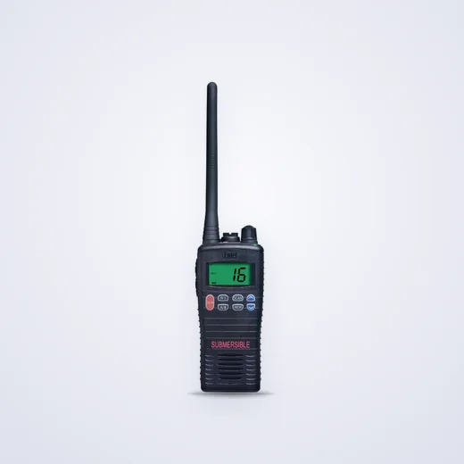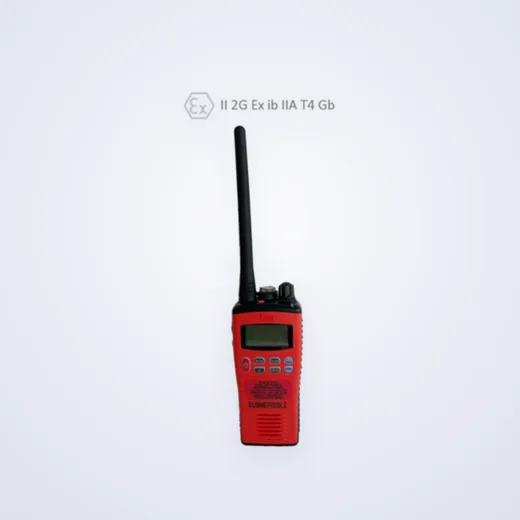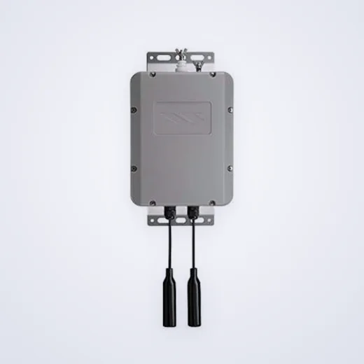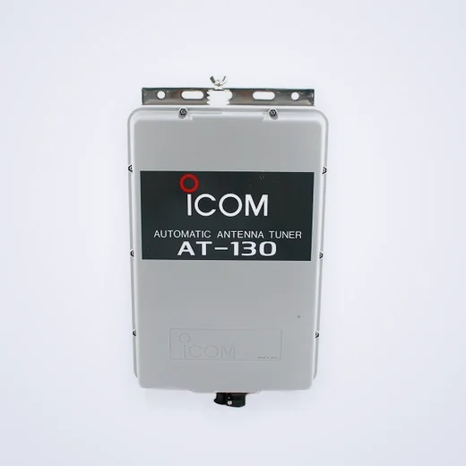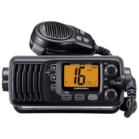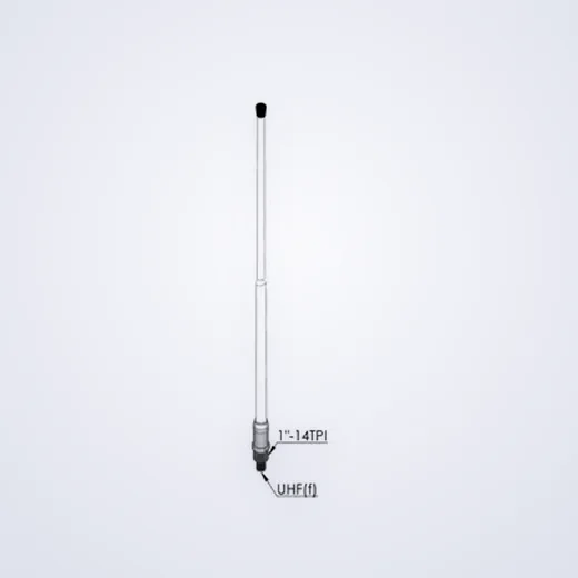
Half of the complaints, “the station is good and there is no connection,” end with an antenna or cable. The station sets the power, the antenna - how much of this power will go into the air and at what distance. Let's take it one by one.
First the range, then everything else.
Marine VHF is operating near 156 MHz, river service communication in Russia - 300–336 MHz. These are different antennas, and the similarity means nothing: a pin designed for 300 MHz on the sea channel gives off a small part of the power, and the rest returns to the station.
Therefore, the first question in the selection is not the length or price, but the working range of the vessel. If both connections are on board, put two antennas and carry them to the mast.
Height decides range
VHF is within line of sight. The range is determined by the height of both antennas, not watts: lifting the antenna a few meters gives more than doubling the power. Hence, the rule of thumb is that the antenna is placed at the highest point, where it does not fall into the shadow of the mast, pipe and radar.
Place of installation: three errors
- Next to the metal structure. Mast, leer, chimney in the near zone distort the diagram: in one direction the ship is heard, in the other - not.
- Slope. The pin antenna works vertically. The tilted one loses coordination with the correspondent's antenna.
- In the plane of the radar radiation. The antenna, which was at the level of the radar scanner, receives a powerful impulse and eventually disables the station's input circuits.
Cable - half the loss
Losses increase with length and frequency. A thin cable, laid “as it turned out”, takes a noticeable part of the power and also weakens the reception. With a long track, take a larger cross-section cable, minimize the bends and number of connectors: each poorly compressed connector is also a point of moisture.
The open deck connectors are sealed. Green ploughing under the tape is a typical reason for "connection of the village for six months."
What's checked on admission
- CSV on work channels - measured at the end of the cable, not "on the antenna";
- the absence of a break and a closure in the tract after stretching;
- mass reliability: for a pin antenna, the body is part of the system;
- Hearing at long and short distances, and not only "turned on".
What to order together
The antenna is usually taken bracket, a segment of cable with connectors and a sealing set. Separately check whether the connector is suitable for the station - the adapter in the tract adds loss and another point of failure.
Where to start a conversation
Tell the type of vessel, range, length of route from antenna to station and height of installation. According to these data, we will select the antenna and cable for the task - the catalog below contains the positions that are available.